🚚 Free Worldwide Shipping on All Orders!Shop Now
Matek CRSF To PWM Converter CRSF-PWM-C
Matek's Industry first CRSF to PWM (Crossfire to Servo) protocol converter adapter boards.
The Matek CRSF-PWM-C converter board has 10 PWM servo outputs. Has built-in 90A continuous current sensor.
Check out our ExpressLRS Collection, all our Receivers and the rest of our Matek products!
Specifications:
Pinouts and Pads
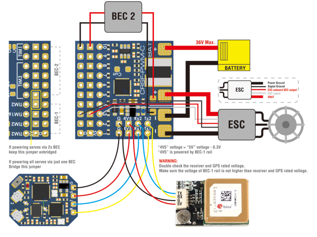
- Tx1/Rx1(UART1) for CRSF protocol Receiver
- Tx2/Rx2(UART2) for GPS/firmware update/setting parameters
- 1~10: CH1~CH10 PWM outputs
- Curr: current sensor signal (0~3.3V)
- Vbat: Battery voltage sensing (0~36V)
- G: ground
- 4v5 pad voltage = 5V pad voltage -0.3V, make sure the voltage on 5V pad is not higher than receiver and GPS rated voltage.
Failsafe
- Failsafe value is set automatically after CRSF-PWM board is powered on and receive CRSF signal. LED blinks 8 times quickly.
- Failsafe value = The PWM value of each channel(except CH3) when CRSF signal is received by CRSF-PWM board for the first time
- CH3 is specially arranged for the throttle, Failsafe value = 988 by default.
- Usually put the Throttle joystick to the lowest point, put AIL(Roll), ELE(Pitch), RUD(Yaw) middle before powering on receiver.
LED status
- slow blinks: CRSF-PWM board doesn’t receive CRSF signal, e.g., receiver is not bound with transmitter, receiver is not connected to UART1 of CRSF-PWM board.
- 8x quick blinks: CRSF-PWM board received CRSF signal and failsafe value is saved.
- solid ON: CRSF-PWM board and receiver are working normally
- 2x slow blinks between 8x fast blink and solid on: CLI mode is active
GPS telemetry
- Compatible with GPS NMEA protocol
- GPS “TX” to CRSF-PWM board “RX” Single wire half duplex UART connection, CRSF-PWM board “TX” to GPS “RX” is not essential.
- Support GPS Telemetry ID: GPS, GSpd, Hdg, Alt, Sats
- u-blox series GPS can output “0+1 – UBX+NMEA” protocol by default
- Sensors(GPS, GSpd, Hdg, Alt, Sats) will blink in Transmitter TELEMETRY tab once CRSF-PWM board has connection with GPS.
- Troubleshooting for no GPS telemetry, double check the wiring between GPS and CRSF-PWM board, some u-blox GPS may don’t output NMEA protcol, you need to be reverted GPS to default configuration in u-center.
- with OpenTX Telemetry Logging, You can plot your flight path or search the lost plane.
TIM & PWM Frequency
- PWM frequency on all 10x Channels can be configured according to TIM
- PWM run at 50Hz by default
- TIM2: CH1, CH2, CH4
- TIM16: CH3
- TIM3: CH5, CH6, CH7, CH8
- TIM1: CH9, CH10
CLI mode
- If CRSF-PWM board doesn’t detect GPS connected to UART2 within 10 seconds after powering on, CLI mode will active.
- After CLI mode is active, CRSF-PWM board can be connected to configurator via USB-TTL module/FC passthrough.
- in CLI mode, CRSF-PWM board firmware can be updated
- CLI mode has no effect to receiver CRSF signal and PWM outputs
Includes
- 1 x CRSF-PWM-C
- 1 x low ESR capacitor
- 1 x Dupont 2.54 pins
$4.50
Original: $14.99
-70%Matek CRSF To PWM Converter CRSF-PWM-C—
$14.99
$4.50Description
Matek's Industry first CRSF to PWM (Crossfire to Servo) protocol converter adapter boards.
The Matek CRSF-PWM-C converter board has 10 PWM servo outputs. Has built-in 90A continuous current sensor.
Check out our ExpressLRS Collection, all our Receivers and the rest of our Matek products!
Specifications:
Pinouts and Pads
- Tx1/Rx1(UART1) for CRSF protocol Receiver
- Tx2/Rx2(UART2) for GPS/firmware update/setting parameters
- 1~10: CH1~CH10 PWM outputs
- Curr: current sensor signal (0~3.3V)
- Vbat: Battery voltage sensing (0~36V)
- G: ground
- 4v5 pad voltage = 5V pad voltage -0.3V, make sure the voltage on 5V pad is not higher than receiver and GPS rated voltage.
Failsafe
- Failsafe value is set automatically after CRSF-PWM board is powered on and receive CRSF signal. LED blinks 8 times quickly.
- Failsafe value = The PWM value of each channel(except CH3) when CRSF signal is received by CRSF-PWM board for the first time
- CH3 is specially arranged for the throttle, Failsafe value = 988 by default.
- Usually put the Throttle joystick to the lowest point, put AIL(Roll), ELE(Pitch), RUD(Yaw) middle before powering on receiver.
LED status
- slow blinks: CRSF-PWM board doesn’t receive CRSF signal, e.g., receiver is not bound with transmitter, receiver is not connected to UART1 of CRSF-PWM board.
- 8x quick blinks: CRSF-PWM board received CRSF signal and failsafe value is saved.
- solid ON: CRSF-PWM board and receiver are working normally
- 2x slow blinks between 8x fast blink and solid on: CLI mode is active
GPS telemetry
- Compatible with GPS NMEA protocol
- GPS “TX” to CRSF-PWM board “RX” Single wire half duplex UART connection, CRSF-PWM board “TX” to GPS “RX” is not essential.
- Support GPS Telemetry ID: GPS, GSpd, Hdg, Alt, Sats
- u-blox series GPS can output “0+1 – UBX+NMEA” protocol by default
- Sensors(GPS, GSpd, Hdg, Alt, Sats) will blink in Transmitter TELEMETRY tab once CRSF-PWM board has connection with GPS.
- Troubleshooting for no GPS telemetry, double check the wiring between GPS and CRSF-PWM board, some u-blox GPS may don’t output NMEA protcol, you need to be reverted GPS to default configuration in u-center.
- with OpenTX Telemetry Logging, You can plot your flight path or search the lost plane.
TIM & PWM Frequency
- PWM frequency on all 10x Channels can be configured according to TIM
- PWM run at 50Hz by default
- TIM2: CH1, CH2, CH4
- TIM16: CH3
- TIM3: CH5, CH6, CH7, CH8
- TIM1: CH9, CH10
CLI mode
- If CRSF-PWM board doesn’t detect GPS connected to UART2 within 10 seconds after powering on, CLI mode will active.
- After CLI mode is active, CRSF-PWM board can be connected to configurator via USB-TTL module/FC passthrough.
- in CLI mode, CRSF-PWM board firmware can be updated
- CLI mode has no effect to receiver CRSF signal and PWM outputs
Includes
- 1 x CRSF-PWM-C
- 1 x low ESR capacitor
- 1 x Dupont 2.54 pins