MicoAir LR900-F 890-915MHz 500mW 27dBm Data Transmit Module For Pixhawk Ardupilot PX4 30KM Long-Range LoRa Telemetry Radio
MicoAir LR900-F 890-915MHz 500mW 27dBm Data Transmit Module For Pixhawk Ardupilot PX4 30KM Long-Range LoRa Telemetry Radio
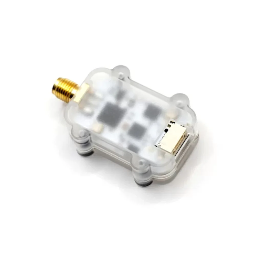
The LR900-F/P Telemetry Radio is a small, cheap radio with superior performance for flight controller that typically allows ranges of better than 30kilometers. And it is very suitable for Pixhawk or other Audupilot/PX4 flight controller. It will connect automatically when power up without any configuration unless you need to implement some special features.
The LR900-F/P works in the 915MHz, so is better to use 2.4GHz receiver than 915MHz receiver (BlackSheep/ELRS 915) on your drones.
Check out all our External Modules/Receivers Collection, and the rest of our MicoAir Products!


Features:
- Works in 915MHz (890-915MHz)
- Small size and light weight (8g)
- Transmit power up to 500mW (LR900-F)
- Base on LoRa modulation technology to obtain excellent anti-interference performance
- Frequency hopping spread spectrum (FHSS)
- Using transparent transmission to compatible with any data and protocol not just mavlink
- CP2102 USB to UART IC, compatible with QGroundControl on Android
Data Transmission
- Transmission Rate: 2.1K Byte/s (default); 1.1K Byte/s; 0.4K Byte/s; 3.2K Byte/s(down) 1.6K Byte/s(up) in FHSS mode
- Maximum Single-package Length: 20K Byte
- Uart Baudrate for JST-GH Interface: 9600; 19200; 38400; 57600 (default); 115200
- Uart Baudrate for USB Interface: 57600 (default); 115200
Physical
- Dimensions: 43.4 x 25.8 x 11mm (without antenna)
- Weight: 8g

Electrical
- Supply Voltage: 5V DC (from USB or JST-GH)
- Average Transmit Current: 200 mA at 27dBm (LR900-F) / 400mA at 30dBm (LR900-P)
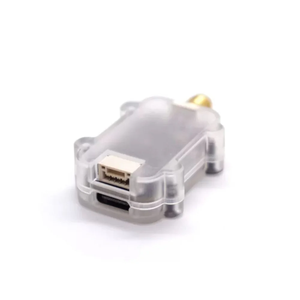
- Serial Interface: 3.3V UART JST-GH1.25-4P
- USB Interface: USB-Type-C (CP2102)
-
Antenna Interface: SMA (Female)

Manual:
LR900-F/P will automatically bind and connect to each other after powering on with default setting, the green LED will always on when connection has completed. It can be used for communication between flight controller and ground station software (Mission Planner or QGroundControl) without any settings.
If some parameters of LR900-F/P needs to be changed, the MicoAisstant helps.
Download the MicoAssistant and Driver
Follow the tutorial to install the CP2102 driver in windows.
Installation Guide for CP2102 Driver Step By Step – MicoAir Tech
After the driver installation is finished, connect the LR900-F to the PC via USB, open the device manager and remember the port number, will need it later.

Setup
Open the MicoAssitant, choose the correct port number of the radio, click “connect” button with baudrate “57600”.

Nothing will happen until you click the “Radio” button.
 Click the “Radio” icon to open the Radio Setup Page, this will only happen when radio elemetry module has correctly connneted to PC and the driver has been installed.
You need to click “READ“ button to refresh the params on the first time. Modify the parameters according to your needs,and then click “WRITE” button to write it into module. The new parameters will take effect after re-power on.
Note that once the baudrate is modified, the new baudrate needs to be used the next time you connect.
Parameter Description
MODE
- DUPLEX (default): Bidirectional communication mode. In this mode, both telemetry can communicate with each other, and only 1-to-1.
- BROADCAST_TX: In this mode, the telemetry can only send data, usually use in RTK base station.
- BROADCAST_RX: In this mode, the telemetry can only receive data, usually use in RTK rover station.
RATE
- LOW:0.4K Byte/s
- MID: 1.1K Byte/s
- HIGH: 2.1K Byte/s (3.2K/s down and 1.6K/s up in FHSS mode)
Only high-speed mode is recommended for flight controller.
CHAN_MODE
- MANUAL: In this mode, need to setup the working frequency manually, 890-915MHz, 1MHz step.
- AUTO (default): In this mode, it will work in a frequency automatically with lowest interference.
- FHSS_GROUND: FHSS mode for the radio telemetry which connect to PC.
- FHSS_AIR:FHSS mode for the radio telemetry which connect to flight controller.
ADDR
Address parameter has a range of 1-30000, and default vaule is 1000, telemetry module can only communicate with each other with the same address value.
CHANNEL
This parameter can only be set in the “MANUAL” CHAN mode, with a range of 0-25, corresponding to 890-915MHz.
BAUDRATE
Baudrate for the JST-GH port, 9600-115200 can be set, and 57600 is default.
USB_BAUD
Baudrate for the USB port, can only be set to 57600 (default) or 115200.
Setup Tutorial Of Telemetry Radio On Ardupilot
Setup Tutorial Of Telemetry Radio On PX4
Connecting Ardupilot to Mission Planner Over LR900 Telemetry Radio
STEP-1
Connect LR900 To Flight Controller
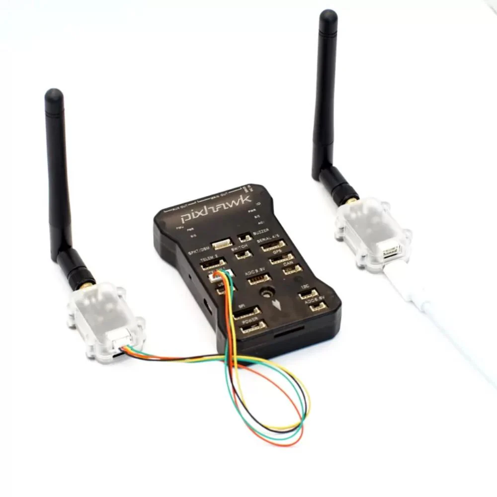
Connect the LR900-F telemetry to the flight controller’s serial port, usually TELEM1 or any other free. Note that the Tx of the LR900-F needs to be connected to the Rx of the flight controller, the same way Rx connect to Tx.
On the Pixhawk1/2 or Pixhawk4/5/6, you can use the cable supplied with LR900 to connect directly.

STEP-2
Configure the controller
The flight controller should first be connected to the computer via USB, and check some initial configurations of it on Mission Planner.
Since the LR900 is connected to the TELEM1, we need to confirm the following settings:
SERIAL1_BAUD=57600(default baudrate of LR900), SERIAL1_PROTOCOL=MAVLink1/2.
If the version of Ardupilot < 4.4.0, you may also need to set BRD_OPTIONS=3 to disable MAVftp.

STEP-3
Install Driver
CP2102 is a USB to UART IC from Silicon Labs and used in LR900-F.
Connect the LR900-F to PC via USB. In the device manager it will show “CP2102 USB to UART Bridge Controller” which means that your PC has detected the drivers but note the “!” sign which indicated cp2102 drivers have not been installed.
Follow our tutorial to install the driver for CP2102.
Installation Guide for CP2102 Driver Step By Step – MicoAir Tech

STEP-4
Connection
If everything goes well, the green LED on both module will stay on, indicating that a connection has been established with each other.
Open the Mission Planner, select the correct port and baudrate (default 57600) in the upper right corner, and then click Connect. It will connect to the flight controller and start reading the parameter lists.

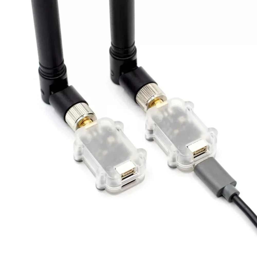
Package Includes:
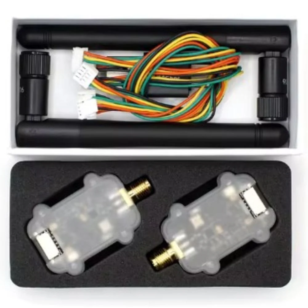
- LR900-F Telemetry Radio Module * 2
- 2 x Antennas
- 1 x wires set
Description
The LR900-F/P Telemetry Radio is a small, cheap radio with superior performance for flight controller that typically allows ranges of better than 30kilometers. And it is very suitable for Pixhawk or other Audupilot/PX4 flight controller. It will connect automatically when power up without any configuration unless you need to implement some special features.
The LR900-F/P works in the 915MHz, so is better to use 2.4GHz receiver than 915MHz receiver (BlackSheep/ELRS 915) on your drones.
Check out all our External Modules/Receivers Collection, and the rest of our MicoAir Products!
Features:
- Works in 915MHz (890-915MHz)
- Small size and light weight (8g)
- Transmit power up to 500mW (LR900-F)
- Base on LoRa modulation technology to obtain excellent anti-interference performance
- Frequency hopping spread spectrum (FHSS)
- Using transparent transmission to compatible with any data and protocol not just mavlink
- CP2102 USB to UART IC, compatible with QGroundControl on Android
Data Transmission
- Transmission Rate: 2.1K Byte/s (default); 1.1K Byte/s; 0.4K Byte/s; 3.2K Byte/s(down) 1.6K Byte/s(up) in FHSS mode
- Maximum Single-package Length: 20K Byte
- Uart Baudrate for JST-GH Interface: 9600; 19200; 38400; 57600 (default); 115200
- Uart Baudrate for USB Interface: 57600 (default); 115200
Physical
- Dimensions: 43.4 x 25.8 x 11mm (without antenna)
- Weight: 8g
Electrical
- Supply Voltage: 5V DC (from USB or JST-GH)
- Average Transmit Current: 200 mA at 27dBm (LR900-F) / 400mA at 30dBm (LR900-P)
- Serial Interface: 3.3V UART JST-GH1.25-4P
- USB Interface: USB-Type-C (CP2102)
-
Antenna Interface: SMA (Female)
Manual:
LR900-F/P will automatically bind and connect to each other after powering on with default setting, the green LED will always on when connection has completed. It can be used for communication between flight controller and ground station software (Mission Planner or QGroundControl) without any settings.
If some parameters of LR900-F/P needs to be changed, the MicoAisstant helps.
Download the MicoAssistant and Driver
Follow the tutorial to install the CP2102 driver in windows.
Installation Guide for CP2102 Driver Step By Step – MicoAir Tech
After the driver installation is finished, connect the LR900-F to the PC via USB, open the device manager and remember the port number, will need it later.
Setup
Open the MicoAssitant, choose the correct port number of the radio, click “connect” button with baudrate “57600”.
Nothing will happen until you click the “Radio” button.
Click the “Radio” icon to open the Radio Setup Page, this will only happen when radio elemetry module has correctly connneted to PC and the driver has been installed.
You need to click “READ“ button to refresh the params on the first time. Modify the parameters according to your needs,and then click “WRITE” button to write it into module. The new parameters will take effect after re-power on.
Note that once the baudrate is modified, the new baudrate needs to be used the next time you connect.
Parameter Description
MODE
- DUPLEX (default): Bidirectional communication mode. In this mode, both telemetry can communicate with each other, and only 1-to-1.
- BROADCAST_TX: In this mode, the telemetry can only send data, usually use in RTK base station.
- BROADCAST_RX: In this mode, the telemetry can only receive data, usually use in RTK rover station.
RATE
- LOW:0.4K Byte/s
- MID: 1.1K Byte/s
- HIGH: 2.1K Byte/s (3.2K/s down and 1.6K/s up in FHSS mode)
Only high-speed mode is recommended for flight controller.
CHAN_MODE
- MANUAL: In this mode, need to setup the working frequency manually, 890-915MHz, 1MHz step.
- AUTO (default): In this mode, it will work in a frequency automatically with lowest interference.
- FHSS_GROUND: FHSS mode for the radio telemetry which connect to PC.
- FHSS_AIR:FHSS mode for the radio telemetry which connect to flight controller.
ADDR
Address parameter has a range of 1-30000, and default vaule is 1000, telemetry module can only communicate with each other with the same address value.
CHANNEL
This parameter can only be set in the “MANUAL” CHAN mode, with a range of 0-25, corresponding to 890-915MHz.
BAUDRATE
Baudrate for the JST-GH port, 9600-115200 can be set, and 57600 is default.
USB_BAUD
Baudrate for the USB port, can only be set to 57600 (default) or 115200.
Setup Tutorial Of Telemetry Radio On Ardupilot
Setup Tutorial Of Telemetry Radio On PX4
Connecting Ardupilot to Mission Planner Over LR900 Telemetry Radio
STEP-1
Connect LR900 To Flight Controller
Connect the LR900-F telemetry to the flight controller’s serial port, usually TELEM1 or any other free. Note that the Tx of the LR900-F needs to be connected to the Rx of the flight controller, the same way Rx connect to Tx.
On the Pixhawk1/2 or Pixhawk4/5/6, you can use the cable supplied with LR900 to connect directly.
STEP-2
Configure the controller
The flight controller should first be connected to the computer via USB, and check some initial configurations of it on Mission Planner.
Since the LR900 is connected to the TELEM1, we need to confirm the following settings:
SERIAL1_BAUD=57600(default baudrate of LR900), SERIAL1_PROTOCOL=MAVLink1/2.
If the version of Ardupilot < 4.4.0, you may also need to set BRD_OPTIONS=3 to disable MAVftp.
STEP-3
Install Driver
CP2102 is a USB to UART IC from Silicon Labs and used in LR900-F.
Connect the LR900-F to PC via USB. In the device manager it will show “CP2102 USB to UART Bridge Controller” which means that your PC has detected the drivers but note the “!” sign which indicated cp2102 drivers have not been installed.
Follow our tutorial to install the driver for CP2102.
Installation Guide for CP2102 Driver Step By Step – MicoAir Tech
STEP-4
Connection
If everything goes well, the green LED on both module will stay on, indicating that a connection has been established with each other.
Open the Mission Planner, select the correct port and baudrate (default 57600) in the upper right corner, and then click Connect. It will connect to the flight controller and start reading the parameter lists.
Package Includes:
- LR900-F Telemetry Radio Module * 2
- 2 x Antennas
- 1 x wires set